
Powered tool tilt
The tilting cylinder changes the working angle of a compatible bucket for slopes and angled profiles.
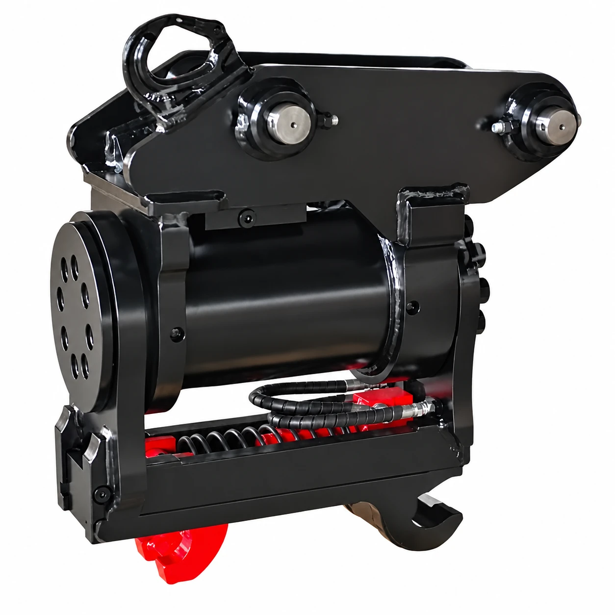
A hydraulic tilting coupler for angling compatible buckets and attachments during grading and finishing. Compare the tilt and locking hydraulic circuits separately; tilt angles vary with the configuration.
A hydraulic tilting coupler for angling compatible buckets and attachments during grading and finishing. Compare the tilt and locking hydraulic circuits separately; tilt angles vary with the configuration.
The tilting cylinder changes the working angle of a compatible bucket for slopes and angled profiles.
A triple-locking retention arrangement secures the attachment pins.
A reinforced slide jaw supports the locking connection; the mechanism combines tilt and attachment interchange.
Check attachment weight, machine size and installation requirements together.
| Specification | Unit | JY-TQ-00 | JY-TQ-01 | JY-TQ-02 | JY-TQ-04 | JY-TQ-06 | JY-TQ-08 | JY-TQ-10 |
|---|---|---|---|---|---|---|---|---|
| Excavator operating weight | t | 0.8~1.5 | 2~3.5 | 4~6 | 7~9 | 10~15 | 20~25 | 28-36 |
| Attachment weight | kg | 56 | 108 | 180 | 210 | 410 | 594 | 1138 |
| Mounting width A | mm | 90-120 | 107-148 | 127-166 | 172-205 | 172-266 | 280-366 | 346-420 |
| Mounting width B | mm | 90-120 | 107-148 | 127-166 | 172-205 | 172-266 | 280-366 | 346-420 |
| Pin diameter C | mm | 25-30 | 35-40 | 45-50 | 45-55 | 60-65 | 70-80 | 90-100 |
| Pin diameter D | mm | 25-30 | 35-40 | 45-50 | 45-55 | 60-65 | 70-80 | 90-100 |
| Minimum bottom width F | mm | 89 | 128 | 138 | 178 | 218 | 288 | 390 |
| Bottom pin diameter I | mm | 25-30 | 35-40 | 45-50 | 45-55 | 60-65 | 70-80 | 90-100 |
| Pickup range J | mm | 84-180 | 158-240 | 200-362 | 272-380 | 300-420 | 350-520 | 500-596 |
| Tilt angle | ° | 180° | 180° | 180° | 180° | 140° | 140° | 120° |
| Tilt circuit pressure | bar | 210 | 210 | 210 | 210 | 210 | 210 | 210 |
| Tilt circuit flow | L/min | 5~16 | 1.8-2.4 | 3.3-6.8 | 7.6-10 | 15-19 | 18-24 | 60-80 |
| Locking circuit pressure | bar | 25~300 | 25~300 | 25~300 | 25~300 | 25~300 | 25~300 | 25~300 |
| Locking circuit flow | L/min | 15~25 | 15~25 | 15~25 | 15~25 | 15~25 | 15~25 | 15~25 |
Confirm all mounting dimensions against the selected machine and attachment drawing. Hydraulic requirements apply only to the hydraulic circuits listed for that configuration.
On smaller screens, swipe the table sideways to compare every model.
Before ordering, send the machine identification and the connection, power and working information relevant to this product.
Excavator model and operating weight
Top and bottom pin diameters and mounting widths
Confirm pin centre dimension E for the selected model
Separate tilt and locking circuit flow and pressure
Tilt clearance and attachment compatibility
No. A tilting coupler changes the angle of the tool; a tiltrotator provides a separate rotation function.
Only when their mounting pins, clearances and locking engagement match the selected lower interface.
Yes. Check the hydraulic circuits and controls specified for each function.
The added height and mass affect reach, clearance and the machine’s lifting limits. Review the complete tool assembly.
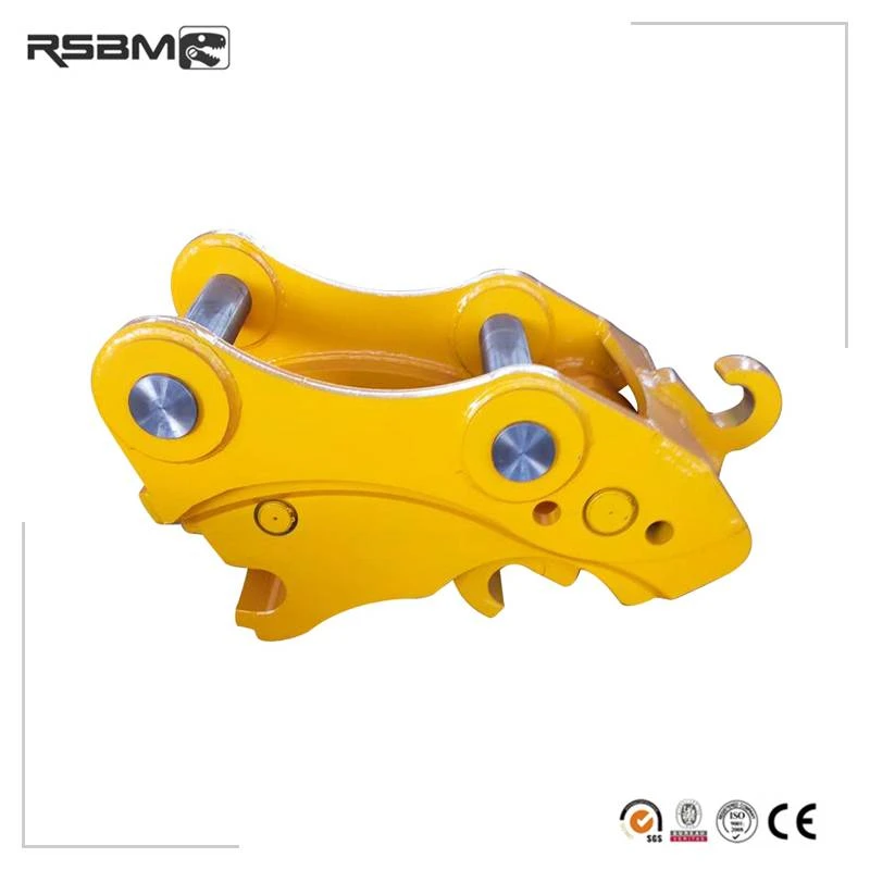
A manually operated pin-grabber coupler for changing compatible excavator buckets and attachments. Compare pin diameter, pin centres and mounting width, then confirm the locking arrangement for the selected machine.
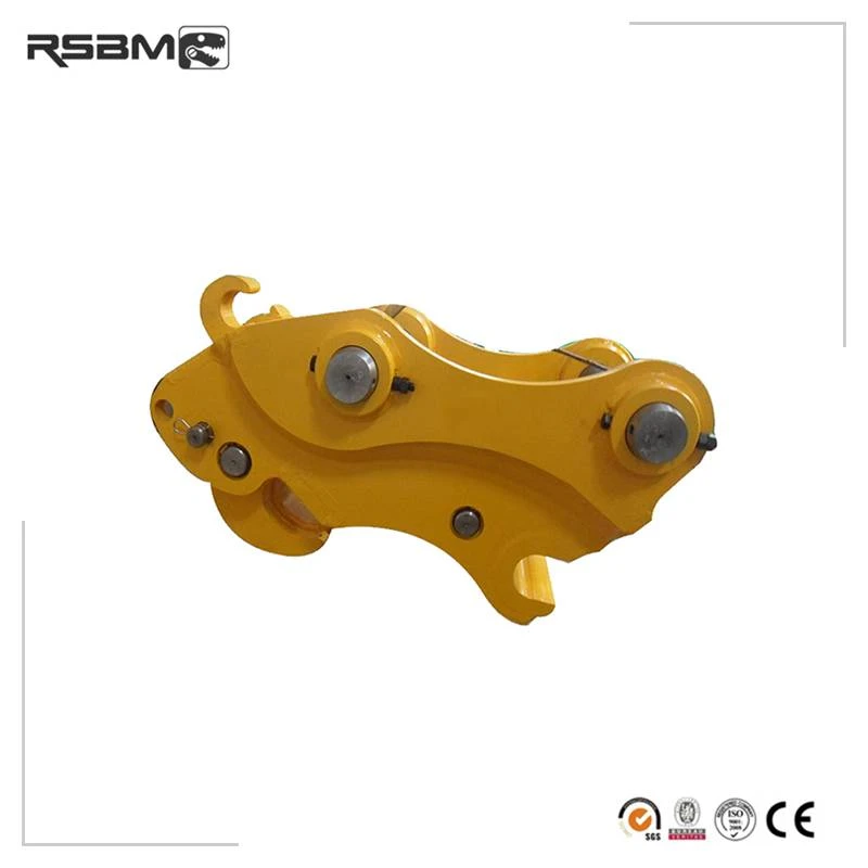
Change compatible pin-mounted buckets and tools with hydraulically operated locking. Check both the mounting dimensions and locking arrangement.
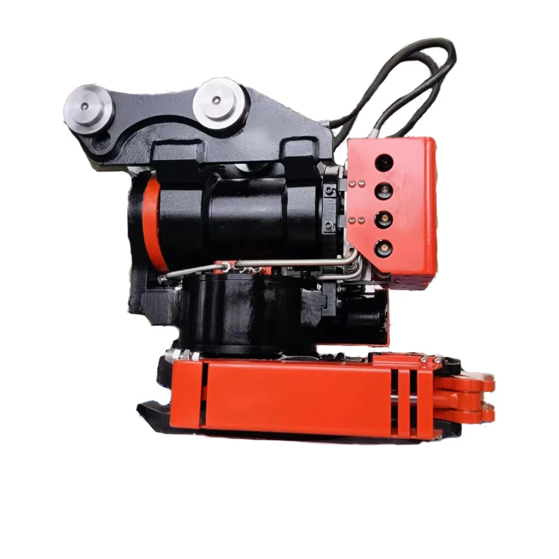
Combine tilt and rotation to position compatible tools around obstacles and finish surfaces from different directions.